This section allows you to view all posts made by this member. Note that you can only see posts made in areas you currently have access to.
Messages - schlumpf
1
« on: 05 July 2020, 08:53:50 pm »
We already exchanged PMs  The mileage is stored in a separate IC on the board (93c46 for those familiar). De-soldering is not that easy due to the nearby plastic frame. The data content is allways the same for all bikes, except the mileage. No protection or coding to a specific ECU or key. Yamaha also provided the programming pads (for production purpose) on the bottom. Quite easy to read/write with a proper (simple) programmer.
2
« on: 25 March 2020, 09:41:20 am »
Some updates.
The add-on circuitry has finally arrived and been attached by Mike. Unfortunatelly it didn't work as expected. Most likely the defective parts on the main board interfere and prevent it to function properly. Seems they have to be removed first. As this is a quite delicate operation we concluded to stop here. For now he's living with a manual switch.
To share our learnings I've put all information into a pdf. Hopefully that gives others some help and guidance. Feedback is welcome. Excuse my english, it's not my first language.
3
« on: 04 March 2020, 04:13:32 pm »
Ready, send me your address via PM please. This is a quick and dirty buildup with parts I had in my box. Cable colours match the dots in the sketch from above. I've tested it good on a salvaged dash (original fan circuit disabled). I had no relay at hand and took a big resistor instead, should not make a difference. Some additional wrapping for isolation and it's good to go
4
« on: 03 March 2020, 05:13:23 pm »
Sorry for my tech talk, I know it's not everybody's world.. But perhaps you find someone nearby to help with the repair?
I could also think about creating a small simple board that's carrying all the parts. As a drop-in module, attached with 3 solder wires?
5
« on: 03 March 2020, 03:56:44 pm »
This is my proposal on how to fix the broken fan activation w/o removing any old parts.
New parts are added on the lower side of the board, no need for complete disassembly, removing the lower compartment of the dash is sufficient.
The circuitry around TR34 is copied and put in parallel to the existing one. This should be fine as it only serves as a simple switch to ground for the relay activation.
Unfortunately there are a few more components to be added than simply TR34.
The replacement parts are best guesses by taking the marking codes, package type and estimated currents and voltages required for this application into consideration. All are non-SMD.
Replacement for TR34 is BC639, 1A/80V.
The proposed diode is a standard 2A/400 silicon type (most likely oversized).
Resistors are uncritical, smallest package with 200mW rating should be fine.
I'm open for discussions and opinions about this solution.
6
« on: 03 March 2020, 11:28:55 am »
That parts looks fine.
But hold on. I'll have a another look to the board this evening. Maybe it's possible to repair from the back side of the board, without removing the old component.
7
« on: 03 March 2020, 09:12:15 am »
Some more results on searching for the "DF" marking of TR34.
Package seems to be SOT-89. Function assumed to be NPN bipolar transistor 80V 1A.
Matches:
2SD1898
TFM5213
2SD1623S
My best guess for replacements:
BCX56
or
BSR43
8
« on: 03 March 2020, 06:58:40 am »
An overall test to locate the failure is quite simple.
- Remove the dashboard
- you see the 16 pin connector, loom side
- locate the green/black cable
- connect it to ground
Fan is running -> failure inside the dashboard
Fan is still dead -> failure in the relay, the fan itself, or the cabling
(edit: correct formatting restored)
9
« on: 02 March 2020, 08:40:40 pm »
One more old picture.
Also I have to correct myself with the part. It's not a BC817 alike due to the package (it's not SOT-23). Must be a bigger type, maybe 2SD1898. That also fits better in terms of current capacity. Have to investigate further tomorrow..
Maybe others out here have a better clue.
10
« on: 02 March 2020, 08:26:08 pm »
Good to see that grommet thinks the same way.
For the dummy-sensor, just pull the connector from the sensor (at the thermostat) and insert the leads of a wired resistor. That mimiks a certain temperature.
The sensor itself is a NTC type and changes resistance over temperature. A few values:
80° = 3700 ohm105° = 1750 ohm120° = 1150 ohm
The dashboard switches to ON below 1750 Ohm, and OFF again around 2000 ohm. There is a small hysteresis (intended).Secondly it switches ON based on a timer (1 minute?, at idle, if you once revved above 1500 rpm). Whatever condition comes first.
For repairing you could "hammer the transistor out", means there is no harm if it gets destroyed. A big blob of soldering tin above all legs and pulling out. I guess it's also glued to the pcb, might need some persuasion. Take care to leave R33 and R34 in position. A good trick is to fix them before with kapton tape, or even mask the whole surrounding. Also very helpfull in case you use a hot air gun, if available.Be carefull with the heat, the copper striped come off easily.
For the transistor replacement you could use almost any NPN transistor. BC817 is a very common type in europe.
11
« on: 02 March 2020, 06:45:26 pm »
Hi Mike,
as you've ruled out all other potential fails, I suspect it's the control circuit inside the cockpit. I've detected and reapired such a defect a while ago. Maybe it's the same in your unit.
The picture shows the affected part of the pcb. Most likely transistor TR34 is not working. Ignore the red coloured parts, that's from another, older discussion about manually activating the fan.
According to the marking code (DF) it's a standard NPN transistor, maybe 2SC2463-F (55V, 100mA) (those markings are not clear without ambiguity). Any similar type should also do fine. Also replacing with a wired (non-SMD) type will work. I know, it's not an easy job..
For testing you could replace the temperature sensor by a wired resistor of less than 1700 ohm. That equals ~105°C. The voltage at anode of D32 should drop from 12V down to ~1.5V, the collector of TR34 accordingly (fan relay or equivalent load must be attached).
Hope that helps.
Regards,Christian
13
« on: 11 August 2019, 12:58:36 pm »
Bit of a thread hi-jack but would you have any recommendations for good books or sources of information on electronics used in motorbikes? Or just good books on basic electronics? A good start might be the following projects. They provide lots of information on their wiki pages: https://forum.arduino.cc/index.php?topic=448191.0http://megasquirt.info/
14
« on: 10 August 2019, 08:03:33 pm »
That is very, very impressive! And I really can imagine how much time and effort went into this project to bring it to such perfection.
I'm working on my multi-gauge for more than a decade and always dreamed of such a brilliant solution. Therefore I'm very curious to learn more about the electronics behind. And maybe I can be of any help and share my learnings with you, to ease up your final work.
Just thinking loud, would it be possible to also add a kind of "Android Window" to run e.g. Google-Maps or maps.me? To have cockpit and navigation in a combined display?
15
« on: 23 July 2019, 07:38:33 pm »
The display is looking great!
Do you have any more details about the HW? What sort of display? Any project space or so? Pictures?
Speed gives 40.3 pulses per meter @ 5V (open collector output, 1k resistor inside the cockpit). Sensor itself supplied with 12V.RPM gives 33.3 pulses @ 1000rpm. Comming from ECU.Duty cycle doesn't matter, frequency is important.
NTC for the fan is 30k @ 25°C, B-value 4000.
Good luck with the project!
16
« on: 17 July 2019, 03:50:28 pm »
I'm not sure about the correct model years. At least the RN01/RN04 designators should fit.The major difference is that RN04 controls the fan via sensor (identical to the FZ1 gen1), RN01 does not.The RN09 sketch is not of relevance here, I just quickly picked what I had available. If I remember correctly the RN09 was the first model introducing a digital bus, no chance to get it working. The mileage is stored inside the cockpit, seems to be a lucky coincidence Anyway, it would be not very difficult to correct it. The speedo sensor (3-wire) gets its 12V-supply from the dashboard. Just check the presence at the far end to be sure. Also the ground wire. The speedo signal (white) reqires a load to work correctly (open collector output type). This load sits inside the dashboard (~2k resistor tied to 5v). Without sensor you should measure 5V on this line (direction towards cockpit). If all is plugged in take a voltmeter and check the signal on the white cable. It should jump between 0V and 5V while rotating the rear wheel. About 40 pulses per revolution.
17
« on: 16 July 2019, 07:12:53 pm »
I've got another comparison chart, maybe that helps better
18
« on: 15 July 2019, 06:28:26 pm »
Maybe this one? 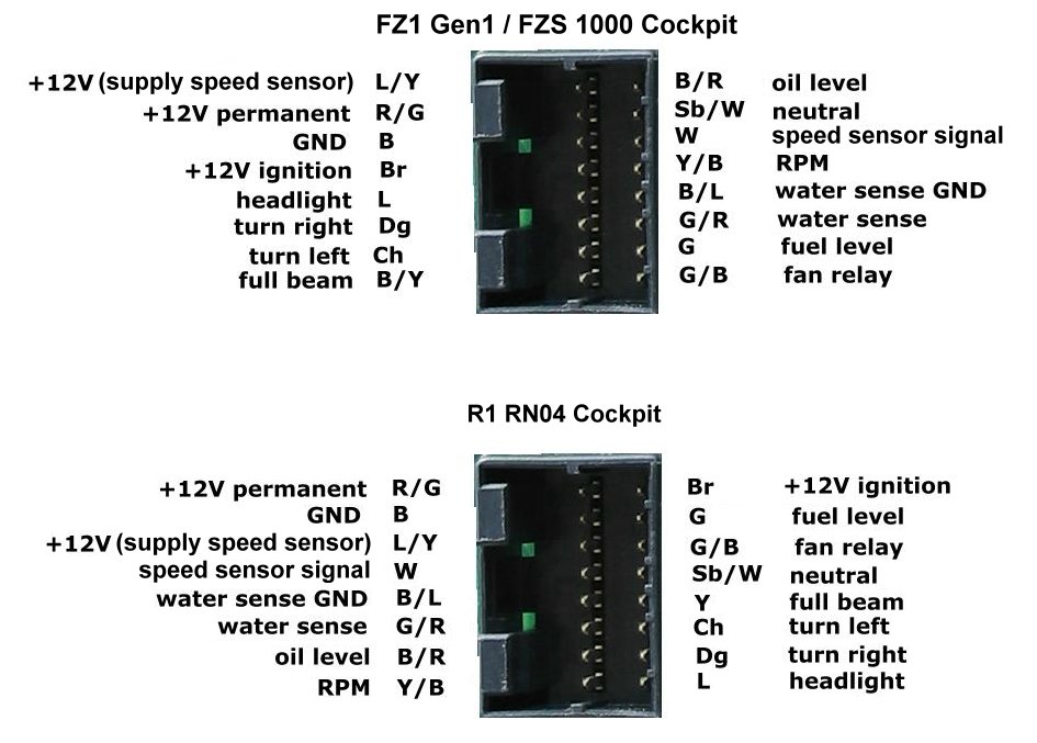
19
« on: 22 June 2019, 03:51:49 pm »
As far as I know it's a 1/8'' Whitworth thread.
20
« on: 05 July 2017, 06:19:53 pm »
There is no option, or hidden menu, to switch the odometer to km (at least to my knowledge). Only way is to re-program the eeprom inside the cluster. If you manage to get hold of such a programmer I can provide you the according hex-file/data.
22
« on: 23 July 2016, 07:41:39 pm »
Here you go.
There is no speedo signal at the clocks, it's a pure digital bus (ECU k-line). But you can tap the speedo signal directly at the sensor. From there it goes to the ECU (main loom).
23
« on: 17 September 2015, 06:26:23 pm »
Just one point to add, maybe you already considered. Use a good soldering tin with a few per cent flux inside. Only this makes the solder to float around the wires the way it should, breakes the oxidated surfaces. And be very quick as the flux vaporizes within seconds. If you wait too long it might appear as if there is too less heat. Fried tin doesn't float at all.
(Hope I got the wording right ..)
24
« on: 05 September 2015, 03:05:19 pm »
The black box fails very rarely, I would push it to the end of the list.
As mentioned before, the ignition barrel is the prime suspect. Same for its cables and plugs. Also remove the protection hosing of the cables, sometimes the cables are fried inside.
Disassemble the barrel and clean the contact plate. The WD40 solution is only temporary.
Second the ignition coils. They might get cracks in the plastic and the spark goes elsewhere. Inspect in the dark and look for discharge/arcs to the frame. Same for the spark caps and cables.
ECU at the end. First swap with a borrowed good one from a friend.
The sticker:
fzs1000
2001 5LV-82305-00
2002 5LV-82305-00
2003 5LV-82305-40 no headlight switch, controlled by ECU
2004 5LV-82305-40
2005 1C2-82305-00
All US models
Fzs1000 & FZS1000s 2001- 2005 5LV-82305-30
Use the 2001, 2002 EU model, matches best to your bike. Newer ones might make trouble with the headlights.
Edit: Assumed your bike is 2001.
25
« on: 28 August 2015, 10:09:17 pm »
Correct, the dummy is used to eliminate the fault code. Fakes identical (electrical) behaviour for the ECU.
The Exup seems to be work the same way since FZR until present.
Do you have the original link for the diagram?
|